Reflective insulation alone cannot prevent heat loss caused by air leaks. Learn how air sealing, proper air gaps, and roof ventilation work together to improve thermal performance under a metal roof.
Even after aluminum foil reflective insulation has been installed beneath a metal roof, indoor temperatures may still be strongly affected by outdoor conditions. The problem is not necessarily the material’s reflective performance. A reflective surface primarily reduces radiant heat transfer. If indoor air can enter the roof cavity through overlaps, roof edges, or service penetrations, heat can still move through the roof with that airflow. Reflective insulation and air sealing address different problems; neither can replace the other.
The key is to establish a continuous air barrier, preserve the air space required by the reflective surface, and separate any designated roof ventilation channels from the indoor space. The aim is to prevent air from bypassing the insulation assembly—not to seal every void in the roof.
Understand What Reflective Insulation Controls—and What It Does Not
The performance of reflective insulation depends on the relationship between a low-emissivity surface and the adjacent air space. Building guidance from the U.S. Pacific Northwest National Laboratory explains that a radiant barrier must face an air space to reduce radiant heat transfer between warmer and cooler surfaces. It controls radiant heat, not heat carried by moving air.
This means that a roof cannot be considered fully insulated simply because the aluminum foil covers the entire area. You also need to identify where air enters, how it moves, and whether it crosses the boundary between the indoor and outdoor environments.
Two different types of air movement should be distinguished:
- Natural convection within an air space: Even without obvious air leakage, temperature differences can cause air to circulate within a cavity. Reflective insulation does not eliminate this process, so its thermal performance depends on the complete assembly—not simply on how shiny the surface is.
- Air leakage through the roof assembly: Air entering or leaving the insulated area through joints, edges, and penetrations carries both heat and moisture. This is the airflow that a continuous air barrier is intended to control.
In winter, warm indoor air leaking toward the cold side of the assembly causes heat loss. In summer, hot outdoor air entering an air-conditioned space increases the cooling load. Although the direction differs, the underlying construction issue is the same: air crosses an enclosure boundary that should be continuous.
Identify the Air Barrier Boundary Before Deciding to Seal the Foil
The location of the air barrier can vary significantly between metal roof assemblies.
In a building with a ventilated attic and insulation above the ceiling, the air barrier separating the occupied space from the attic should generally be located at ceiling level. In this arrangement, the reflective layer beneath the roof does not necessarily serve as the indoor air barrier. A roof design report from Building Science Corporation states that a ventilated attic should be separated from the conditioned space by an air barrier at the ceiling.
If the insulation follows the roof slope, the air barrier must remain continuous along the corresponding roof enclosure assembly, including its connections to walls and its treatment around penetrations. An air barrier is not an isolated sheet of membrane; it is a system made up of materials, seams, and connection details.
Construction drawings should therefore identify at least three elements:
- Which layer reduces radiant heat transfer.
- Which layer controls air leakage.
- Which cavity provides the required ventilation and drying.
Some of these functions may be provided by the same material, or they may require separate layers. However, a single reflective membrane should not automatically be assumed to perform all three functions. In particular, a reflective membrane with unsealed seams and unconnected edges cannot be considered a continuous air barrier simply because it provides full coverage.
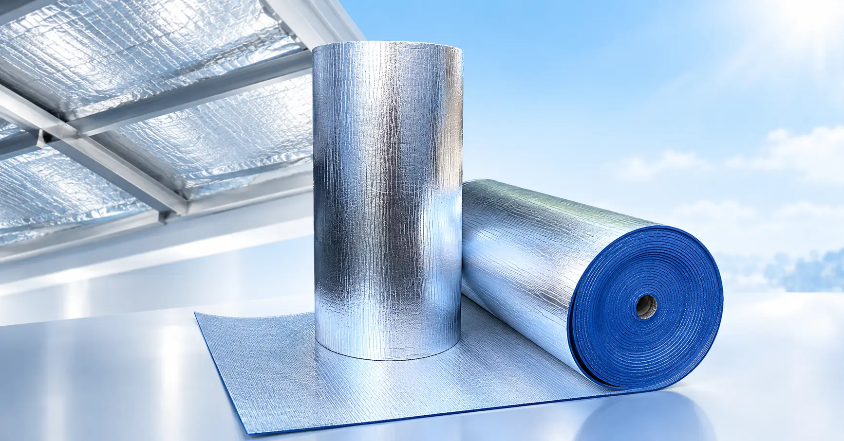
The Reflective Surface Needs an Air Space—but Bigger Is Not Always Better
Pressing aluminum foil tightly against adjacent materials to reduce air movement can compromise the conditions it needs to function as reflective insulation. The reflective surface must face an effective air space. Without that space, it cannot provide the same reduction in radiant heat transfer.
The Australian Government’s Your Home guide recommends an air gap of at least 25 mm beside the shiny surface of reflective insulation and identifies 45 mm as ideal. These are installation recommendations from that guide, not universal dimensions that can be applied to every metal roof system. The required gap should be determined from the selected product, assembly design, and relevant thermal performance data.
During installation, avoid two opposite mistakes:
- Compressing the reflective surface against insulation or other components to “reduce convection,” thereby eliminating the effective air space.
- Increasing the cavity size arbitrarily to “improve insulation” without verifying the thermal performance of that assembly. Reflective insulation performance depends on heat-flow direction and air-space conditions, not gap thickness alone.
Installation checks should also go beyond measuring the gap at a single location. Flexible materials should be secured according to the manufacturer’s requirements, and the specified air space should remain in place after installation. An air gap shown on a drawing is of little value if large areas of the reflective surface end up touching adjacent materials.
The relevant measure of performance is the completed assembly—not an uninstalled roll of material.
Control Air Leakage at Overlaps, Perimeters, and Penetrations
The effectiveness of an air barrier often depends more on its connection details than on the material across the main surface. Seams, corners, and service penetrations can interrupt the continuity of the air-control layer. A supported flexible membrane can form part of an air barrier, but its seams and connections must be sealed.
Overlaps: Overlapping Is Not the Same as SealingOverlapping two sheets provides coverage. Preventing air from passing through the joint requires a reliable sealed connection. If the membrane is intended to serve as the air barrier, the construction documents should specify how the seams are to be sealed rather than simply stating “install with overlaps.”
Tape, sealant, overlap dimensions, and substrate preparation should follow the requirements of the selected system. No single aluminum foil tape or overlap width should be presented as a universal solution for all reflective membranes.
Your Home also emphasizes installing insulation according to the product instructions to minimize performance losses and risks such as condensation and fire.
Perimeters: Connect the Roof Air Barrier to the Adjacent Air BarrierA reflective membrane installed continuously across the main roof area does not necessarily create a complete enclosure boundary. The important question is whether it connects to the designated air-control layer at the eaves, gables, and roof-to-wall junctions.
An air barrier controls the entire boundary between indoors and outdoors—not just the central area of the roof.
If the installer cannot explain where the membrane edges will ultimately be sealed, the connection details should be reviewed before continuing with isolated tape repairs. Patching individual gaps cannot replace a complete, continuous connection path.
Penetrations: Every Opening Needs Its Own Sealing DetailPipes, cables, exhaust ducts, and other services interrupt the air barrier wherever they pass through it. The Australian Building Codes Board’s condensation management handbook identifies service pipes, drainage pipes, cables, flues, and ducts as typical penetrations that can affect the effectiveness of an air-control layer.
These locations need sealed connections suited to the assembly. Cutting the membrane so that it merely appears to fit closely around a pipe is not sufficient.
For flues and other high-temperature components, the relevant fire safety and installation requirements must also be followed. Details using ordinary membranes or tapes must not be applied to these locations without confirming their suitability.
Do Not Block Roof Ventilation to Prevent Convection
Airtightness and ventilation are not contradictory. The air barrier controls indoor air moving through the building enclosure, while ventilation channels allow air to follow a designed path on the exterior side of the assembly or within an unconditioned cavity. These functions should remain separate rather than cancel each other out.
For ventilated attics, the Pacific Northwest National Laboratory’s radiant barrier installation guidance makes clear that installing a radiant barrier does not require cutting off attic airflow. For the relevant below-rafter installation method, ventilation paths at the eaves and ridge should remain open.
For a metal roof, the key question on site is not “Is there airflow here?” but “Does this airflow cross the insulation and air barrier boundary?”
- Air moving along a designated ventilation path should not be blocked simply because airflow is present.
- Outdoor air entering fibrous insulation and causing wind washing should be controlled by an appropriate exterior air-control layer.
- Indoor air entering a cold-side cavity through ceiling or roof-slope connections should be stopped at the relevant air barrier—not by sealing exterior ventilation openings.
“Wind washing” refers to outdoor air passing through or disturbing insulation in a way that reduces its thermal performance. Preventing wind washing and maintaining roof ventilation can be achieved together, provided ventilation air does not enter or bypass the insulation area that should be protected.
Seal Air Leakage Paths While Preserving Appropriate Moisture-Drying Paths
Air leakage carries moisture as well as heat. This is particularly important for metal roofs. CSIRO’s technical guidance on condensation notes that radiative cooling can lower a metal roof’s temperature below the outdoor air temperature. Moist air contacting the cold surface may then form condensation.
Reducing the movement of humid indoor air into the roof cavity can help control condensation risk. However, this does not mean that adding a vapor-impermeable foil layer at any location is safe.
Airflow control and vapor diffusion control are separate design tasks. Membrane placement and vapor permeability should be selected according to the climate, indoor humidity, and available drying paths within the roof assembly.
If the existing assembly already includes a strong vapor-control layer, adding another vapor-impermeable material without assessment may alter its ability to dry. Before adding a foil layer during renovation, identify the existing construction layers rather than considering only the reflective performance of the new material.
Before Closing the Roof, Check the Entire Continuous Boundary
To assess whether air leakage may compromise the performance of reflective insulation, inspect the designated air barrier boundary section by section—not just the foil for holes.
Check the following:
- Does the reflective surface still face the specified air space? Are there areas where it touches adjacent materials or where the gap is missing?
- Have the air barrier overlaps been sealed as specified, and are the perimeter edges connected to the adjacent air-control layers?
- Do pipes, ducts, cables, and other penetrations have complete sealing details?
- Are the required ventilation paths unobstructed, without allowing air to enter the indoor space or pass through the insulation?
- Do the membrane’s vapor-control properties and installation position comply with the roof’s condensation-control design?
At inspection, “fully covered” confirms coverage—not continuity of the air barrier. Likewise, “fully sealed” does not prove that ventilation and moisture management have been addressed correctly.
For reflective insulation beneath a metal roof to perform consistently, three conditions must be maintained: the reflective surface must face an effective air space, unintended airflow paths across the indoor–outdoor boundary must be eliminated, and the roof’s required ventilation and drying paths must remain functional.

