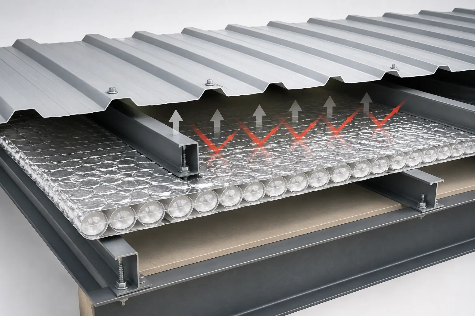
For metal roof applications, reflective insulation should be installed with a controlled air space adjacent to the low-emissivity surface. Seal all side laps, end laps, penetrations and perimeter details to limit unwanted air movement within the reflective cavity. Where roof ventilation is required, keep the ventilated drainage plane separate from the enclosed reflective air space to reduce convective heat loss while maintaining moisture management.
When installing reflective insulation under a metal roof, the key to preventing heat loss caused by air convection is not to seal every cavity completely. Instead, the reflective-insulation air cavity and the roof ventilation/drainage cavity should be designed as separate systems.
The air space next to the reflective insulation should be as continuous, sealed, and low-airflow as possible. In contrast, the roof ventilation cavity must maintain an uninterrupted airflow path from the eaves to the ridge. These two cavities serve different functions. Combining them into one space often compromises insulation performance, moisture control, or condensation prevention.
First, distinguish the different air spaces
Many installation problems occur because all air spaces are treated as if they perform the same function. In a metal roofing system, there may be at least three different types of air spaces:
| Air space type |
Main purpose |
Is strong airflow allowed? |
Key design requirement |
| Reflective-insulation air cavity |
Reduces radiant heat transfer and limits conductive and natural convective heat flow |
No significant airflow |
Continuous cavity, sealed edges, controlled thickness, reflective surface facing the cavity |
| Roof ventilation cavity |
Removes hot and humid air, lowers roof temperature, and controls moisture |
Yes |
Intake at eaves, exhaust at ridge, uninterrupted ventilation path |
| Interior air-barrier layer |
Prevents warm, moist indoor air from entering the roof assembly |
No air leakage |
Sealed overlaps, sealed transitions, and properly treated penetrations |
A reflective surface needs an adjacent air space to reduce radiant heat transfer. However, if that air space is connected to outdoor or indoor air and allows strong air exchange, convective heat transfer will increase and reduce the effective thermal resistance of the assembly.
At the same time, the ventilation cavity above or within the roof assembly should not be blocked by reflective insulation, because that cavity is responsible for releasing moisture and excess heat. Installation guidance from PNNL Building America also emphasizes that radiant barriers primarily address radiant heat transfer rather than convective heat transfer, so they should not block existing attic ventilation paths. Ventilation should remain available at both the ridge and eaves.
Core methods for controlling convection
1. Create a controlled air cavity with battens, purlins, or a slight material sag
For metal roofing, reflective insulation should not be installed tightly against the metal roof sheet. If the reflective surface is in direct contact with the roof panel, it no longer faces an air cavity and its radiant heat-control performance is significantly reduced.
However, the cavity should also not become an excessively deep and fully open void.
A practical method is to use purlins, timber battens, hat channels, Z-purlins, or the natural sag of the insulation material to create a controlled air cavity of approximately 19–25 mm (3/4–1 inch). This range generally allows a low-emissivity surface to reduce radiant heat transfer while limiting excessive natural air circulation within the cavity.
Some metal-roof reflective insulation installation guides specifically recommend fixing the material to purlins while allowing approximately 3/4 inch of sag. This creates an air space between the roof sheet and the insulation. Adjacent seams should then be sealed with reflective tape.
A typical assembly may be arranged as follows:
Metal roof sheet → approximately 19–25 mm controlled air cavity → reflective surface → double-bubble / XPE / aluminum-foil composite insulation → interior side or main bulk insulation layer
The purpose of this air cavity is to remain stable and low-airflow. It should not function as an open ventilation channel.
2. Control air-cavity thickness: thicker is not always better
Once an air cavity becomes too deep, temperature differences can drive natural air circulation inside the cavity. Warm air rises while cooler air falls, creating a convection loop. This airflow carries heat from the warmer side toward the colder side and reduces the thermal resistance that the air layer would otherwise provide.
A practical approach is:
- Less than approximately 13 mm: The air gap may be too narrow for consistent installation and may reduce the effectiveness of the reflective surface.
- Approximately 19–25 mm: Suitable for many metal-roof reflective insulation assemblies.
- Approximately 25–50 mm: Can be used, but cavity subdivision, edge sealing, and thermal-bridge control become more important.
- More than approximately 89 mm: Should not be treated as a high-R-value “still air layer.” Use bulk insulation such as fiberglass, mineral wool, PIR/PUR board, or spray foam as the primary insulation material.
Under ASHRAE/ICC air-space calculation principles, air spaces smaller than 0.5 inch are generally not assigned an R-value. Likewise, air cavities larger than about 3.5 inches should not be assumed to provide proportionally higher R-values, because natural convection becomes more significant as the cavity depth increases.
3. Seal longitudinal seams, cross seams, and cavity ends
Convective heat loss often does not occur in the middle of the insulation sheet. It usually occurs at overlaps, eaves, ridges, roof-to-wall connections, and penetrations.
If warm, moist air can enter the air cavity behind the reflective insulation, it can circulate within the cavity, increasing heat loss and condensation risk.
During installation:
- Seal longitudinal overlaps with compatible aluminum foil tape or reflective insulation tape.
- Seal transverse seams as well; do not treat only the long-side overlaps.
- Use pressure strips, sealing tape, sealant, or compatible closure accessories at ridges, eaves, parapets, gable ends, and edge terminations.
- Seal around roof-sheet fasteners, pipes, vents, skylights, flues, support brackets, and other penetrations.
- Maintain continuity between wall air barriers and roof air barriers.
- Avoid tears, punctures, exposed cuts, damaged surfaces, and unsealed openings.
Metal-building condensation-control guidance commonly identifies side laps, end laps, door and window transitions, foundation terminations, and other air-barrier details as critical locations. If the air barrier or vapor-control layer is interrupted at purlins or connections, air and water vapor can pass through the assembly.
Tape selection is also important. Tape intended for airtightness or vapor control must be compatible with the facing material. Metallized PET film, pure aluminum foil, white PE film, and woven-fabric composite facings have different surface properties and adhesion requirements. It is not enough to choose a product simply because it is labeled “aluminum foil tape.”
For export projects, it is advisable to request that the supplier provide both the main insulation material and the matching tape system, together with data for peel strength, temperature resistance, heat-and-humidity resistance, and aging performance.
4. Separate the ventilation cavity from the reflective-insulation cavity
This is one of the most important design principles in metal roofing.
If the eave-to-ridge ventilation channel is directly connected to the air cavity next to the reflective insulation, outdoor air can move rapidly across the reflective surface. In that situation, the reflective surface may still reduce radiant heat transfer, but the insulation value of the air cavity will decrease significantly.
In winter, the airflow may also carry cold outdoor air deeper into the roof assembly and increase heat loss.
A more effective approach is:
- Provide a continuous ventilation path on the exterior or upper side of the roof assembly.
- Create a relatively enclosed, low-airflow cavity on the interior side of the reflective insulation.
- Separate the two spaces using the roof panel, breathable membrane, underlayment, purlin system, or another appropriate construction layer.
- Prevent the ventilation cavity and reflective-insulation cavity from connecting at edges, openings, or penetrations.
This can be understood as a “two-channel” design:
- The ventilation channel removes hot and moist air.
- The reflective-insulation cavity allows the low-emissivity surface to reduce radiant heat transfer.
- The interior air barrier prevents warm, humid indoor air from entering the roof system.
- Each layer has a separate function. One large open cavity should not be expected to perform all three roles at the same time.
Thermal bridges can worsen the problem
In metal roof systems, steel purlins, screws, fixing strips, channels, framing members, and connectors conduct heat much more readily than air cavities or bubble-insulation materials.
Even if the reflective air cavity is properly designed, direct metal connections between the exterior and interior sides can create significant thermal bridges.
Recommended measures include:
- Install a continuous thermal-break layer between the metal roof sheet and interior structural components where practical.
- Use thermal-break pads, insulated purlin spacers, thermal blocks, or thermally separated fixing systems.
- Reduce unnecessary metal penetrations through the insulation layer.
- Avoid compressing or damaging the reflective insulation with fixing strips in a way that creates a continuous conductive path.
- Evaluate screws, ridge details, edge flashings, doors, windows, and roof penetrations as part of the thermal design.
Reflective insulation can reduce radiant heat transfer, but it cannot independently solve serious thermal bridging through metal framing. In winter condensation cases, thermal-bridge locations often reach dew-point temperature before the larger insulated areas do.
Common installation mistakes
Installing the material tightly against the metal roof sheet: The reflective surface has no adjacent air space, so its radiant-barrier function is greatly reduced.
Leaving a large open cavity: Natural air circulation increases, allowing heat to be carried through the cavity by convection.
Sealing only longitudinal overlaps: Air can still enter from ends, penetrations, and unsealed cross seams, creating a pathway for heat and moisture movement.
Connecting the ventilation channel directly to the reflective-insulation cavity: Ventilation may improve moisture removal, but the thermal resistance of the reflective air cavity is reduced.
Using reflective insulation as the only insulation layer: In cold climates or buildings with specified R-value requirements, reflective insulation alone will usually not meet the required thermal performance.
Ignoring indoor humidity: In high-humidity buildings—such as workshops, livestock facilities, laundries, swimming pools, food-processing rooms, or similar spaces—warm indoor moisture can enter a cold roof assembly and condense if there is no continuous air and vapor control layer.
Assuming all aluminum foil tapes provide permanent sealing: Tape can fail if it is incompatible with the facing material, installed at low temperatures, applied to dusty or oily surfaces, exposed to UV, or subjected to prolonged heat-and-humidity aging.
In short, effective metal-roof reflective insulation depends on a controlled, sealed, low-airflow air cavity next to the reflective surface; a separate, continuous ventilation cavity for heat and moisture removal; and a continuous interior air barrier to stop warm, humid air from entering the roof assembly.


